Sunday, October 21, 2012

Alidade


 This is final Alidade for the Exploratorium is based off of the Osborne Fire Finder and my initial cardboard model.  It is 19.5'' in diameter and composed of machined aluminum, machined phenolic as well as glass and acrylic.   It's seen sitting in the Pier 17 window (in SF) on our mock up rail, so the map in this case does not correspond to the viewable landscape as it will when placed in the Exploratorium's new Observatory Gallery at the end of the pier and one story up. Below are a few additional preliminary photos of the Alidade.


 As these were the first photos taken of the finished alidade, the map disk and point ring are made of paper and not the etched and printed aluminum that will be in the finalized exhibit. On the upper part of the map disk you can see a map of the San Francisco waterfront. On the lower part there is the color coded zone diagram which separates the view into various districts. The acrylic ruler that spans the two sights indicates the line of sight as seen in plan (normal map) and in section (zone diagram). The ruler is also graduated to indicate the approximate distance between the observer (at the center of the map) and the landmarks being viewed on the water front map. The small pocket in the lower sight indicates the initials of the landmarks being viewed so they can be looked up in an accompanying book which will provide information on the landmark's historical context and how it relates to the district in which it resides.   Currently, the design of the book is in progress, so is not pictured here.      


Heres another detail of the map and the line of sight rule.


Here is a view of the near sight and the point indicator gauge, the bearing angles are also indicated below the zone diagram.

A view of the far cross hair sight.

Rangefinder #3 model

This is a "looks like" model for the final Rangefinder, which will contain a mechanism similar to Range Rinder #2, but is asymmetrical.  It's made of hand perfected cardboard rolled around laser cut internal ribs and then affixed with gum tape.


Here are a few interface models I made to explore the positioning on the three major interactive components, the eyepiece (on the left), the range gauge (middle) and the ranging knob (to the right). The two armed model on top came from looking at British Barr and Stroud rangefinders. The final model ended up not including the right arm after the discovery of some asymmetrical Swedish rangefinders.


This is the view from behind the rangefinder. You can see the eyepiece in the center with the range gauge to right and finally the ranging knob on the far right. 


Looking form the front you can see the two prism ports where you vision would be directed out of the rangefinder.

Prayer Wheel (stroboscopic)

This was another device that came out of my experiments with Jisho Roche Adachi, a small and simple platform for short animations the Stroboscopic Prayer Wheel. 


Here is the prayer wheel in some initial drawings in Jisho's notebook, the white scrap of paper on the left of the book is the strobe trigger I planned to use.

The basic structure of the prayer wheel consists of an acrylic tube with laser cut plywood end caps.  Bearings were pocketed into the end caps allowing a threaded rod to be inserted through the wheel's body and the maple handle while still allowing the body to spin freely.

Here are the guts of the wheel, you can see the control circuit suspended above the lower plate which has a series of 8 magnets to trigger the strobe.  Three leds were mounted above the control plate and pingpong balls were stuck over them to act as diffusers, so the light would be distributed evenly.   


Finally, a weight consisting of washers and felt disks to prevent damage to the acrylic was added making it possible to spin the wheel by tipping your wrist slightly as in traditional Tibetan Prayer Wheels.


With the mechanism complete we added an eight frame velum animation sequence, to produce this very satisfying result.  

Friday, October 12, 2012

Turn table animation machine

I built this animation machine in collaboration with Jisho Roche Adachi  for  an Exploratorium event focused on time. Jisho an Illustrator / Painter and an old friend who happens to share an interest in animation machines. You can see more of Jisho's work here .  Though originally we wanted to explore using a prism shutter similar to high speed cameras, we tried using a rotating cube and later hexagonal prism which I milled out of an acrylic rod.


Shutters were supposed to spin with a wheel on the turntable (as seen in Jisho's notebook below). These prism wheels proved very hard to synch up and were abandoned after the first few days. 


 The physical design of this project ended up drawing directly from the Electrotachyscopes which I built as a student at Oberlin and the later point source projector project . The machine uses an improved electrotchyscope strobe circuit and laser etched mirror disks based off the the point source projector's slides.


The Electrotachyscopes used an optical gate trigger for the strobe which was less than reliable. For this machine I used neodymium magnets in pockets in the record platen and a reed switch in the tone arm.  This design really stays true to the record player's original form and function. The reed switch in the tone arm reads the magnets and tells the strobe to fire only when its placed over the side of the platen.  We started out with a simple ring of 12 magnets around the edge of platen. However, as this was an automatic turntable we were able to take advantage of the 7'' and 12 '' settings to play different strobe rate "tracks" in the platen. In the photo above there is an inner track of 12 flashes per rotation and an outer of 18 flashes per rotation. Due to the position of the strobe circuit, we ended up shortening the tone arm,  but if we had been able to leave it full length we may have been able to use the 10'' setting for  a third strobe track.       

Here is a detail of the strobe circuit with the adjustable Locline light arm and trigger wires running to the magnetic reed switch in the tone arm.  


Here is the machine playing a 12 frame Muybridge animation sequence as seen on the machine's movable velum screen.


Projection detail.


In another adaptation we added a spool to the top of the platen allowing it to play a loop of acetate Jisho had drawn based on video of people walking around the Exploratorium. We discover that this format could either be used to animate the film itself by shining the light through the screen behind it or as a simple shadow projector by placing the moving film between the led light arm and the screen.  


Tuesday, August 28, 2012

Cylindrical Perspective Window


The cylindrical perspective window is a drawing tool which allows a used to trace the local landscape in near perfect perspective. As another Exploratorium prototype, it based off the museum's existing perspective window. The original is a flat window to draw on with a fixed eyepiece, my version uses a curves sheet of lexan instead of flat glass which makes the entire drawing surface the same distance from the eye.  Optimally one would use a spherical window so all points were equidistant from the eye.  However, because this window is for drawing landscapes in the far field, most of the drawing happens in the middle of the window so a cylindrical window makes decent approximation of a sphere as long as you do not draw at the upper of lower edges of the window.

I decided to use a slot made of laser cut acrylic with a chin rest instead of a round hole for the view port as it avoids the need to adjust the height of the eyepiece. The rest of the perspective window is made of plywood cut on a cnc router, maple dowels and the legs are made from some cardboard tubes from butcher paper rolls. The window structure has a series of plugs that fit into the cardboard legs holding them on securely but also allowing legs a base plate to be removed for easy storage.    


 The curved window widens area you can draw on without distorting the image horizontally, making very wide angle drawings possible.


Here is an image of a drawing taken from above and to the left of the original eye position.


Wednesday, March 21, 2012

Point Source Projector


In my continuing quest for a brighter cheaper simpler projector for the graffiti projector concept, I realized that going lensless is the only way to really achieve this.  Lenses are in my experience cheap when they don't meet your specifications and expensive when they do. On top of that you have to build a precise structure to keep them aligned and usually need more than one for good image quality. I first encountered the idea of a point source projector when I read about Jim Sanborn's Cyrillic Projector you can read more about it here (the pieces A Comma and Lux use a similar technique).


The most basic way to achieve this is to get a very small bright light source and shine it through a cut out. This works well and gives the theoretically maximum brightness at the cost of having no control over throw length.  The closer the projection surface to the projector the brighter and smaller the image. You can't get a bright image very far away as the brightness is governed by the inverse square law. While this is not a great characteristic it is tolerable for the short throw applications I had in mind. The real problem with cutouts is the typical stenciling problem of islands created when you have concentric rings of positive and negative space as seen above.


You can solve this by using a grid of separate half tone dots or using a simplified image with bridges as in a typical stencil, like the A above.  I didn't want to do that much post processing of images, so instead I look to another familiar print making technique screen printing.  Screen printing avoids the problems of islands by suspending the masked zones in the permeable matrix of the screen.  After thinking about this for a bit I wondered if it might be possible to make a plexiglass mirror selectively reflective, by removing the reflective backing in places and relaying on the acrylic to act as the matrix.  Sounds simple but I wasn't at all sure it would work.  I could print some resist on the back and sand blast it, or laser etch it and risk warping and melting.  In the end I went for laser etching, what I found was that as long as the image was not to detailed the mirror would not warp or melt significantly.


Here was the first attempt (I believe it was a picture of Hamilton) turned to be too much detail and the mirror backing oxidized and the acrylic warped.


Here was second one I tried it didn't warp but the mirror back didn't get completely clean in the negative space either.


To use the projector you just have to shine your point source at the etched mirror at a shallow angle.
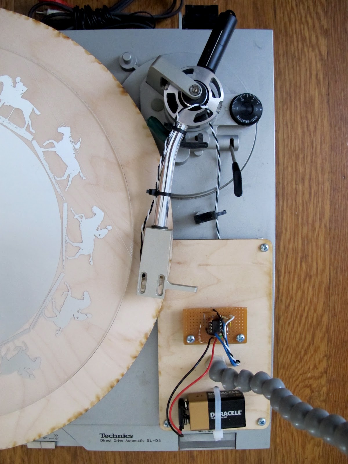
I used loc-line coolant hose to allow easy adjustment of the light sources position, and made a simple wooden platform to hold the mirror slide and the led driver.  The led I used was the brightest and smallest one I could find, a Cree xp-g lamp it has a 3mm emitter and driven at .75 to 1A can throw a clearly visible 5' image from about 10' in dim light.


Here's a detail of the led and its aluminum heat sink cube.


Here is a detail of the mirror slide projection. It achieves finer detail than a cutout, but still has its defects, you can see patches of oxidation at the bottom of the letters and in general the image can't achieve the crispness of a stencil projection. What is Dec, unremarkably I needed some short words and happened to be making it last December so decided to use Dec in the most decorative gothic font I could find.  
                  

Friday, March 9, 2012

Monocular


I was asked by the Exploratorium to design a minimalist telescope that might be used in the new building (the Exploratorium is moving from the Palace of Fine Arts to Pier 15) . This was my first attempt, an open framed 3.5x Galilean telescope. I attached the focusing screw to the objective lens not the eye piece (which is typical) to further simplify the design. Galilean telescopes have the advantage of producing an upright image with only 2 lenses but suffer from high distortion above 3x.


Looking through the scope, the spherical distortion and chromatic aberrations are notable, especially if the scope is poorly focused. I ended up using 1/4''-20 threaded rod for the focus adjuster, this was way too fine for accurate focus control as it was hard to tell if you were getting more or less focused in less then 5 or 10 turns of the knob.


Given the image quality problems with the Galilean scope I made this "looks like" model for a monocular using Keplerean optics using 8020 aluminum stock and laser cut cardboard. A Kepler style scope produces a clear but inverted image, so the model included a pentagonal case that was scaled to hold erecting prisms to un-invert the image. To solve the slow focus problem I modeled a transverse focus knob like a microscope capable of moving the objective lens quickly but precisely.


Tracing Camera Prototype


The Exploratorium asked me to prototype a portable camera obscura for the new building to be used as a tool to make observations and draw the local landscape.  It is a very optically simple device consisting of a box with a lens mounted in front of a 45 degree mirror inside to flip the image right side up and a piece of glass on top onto which tracing paper can be placed to receive the image.     

Originally the tracing camera was mounted on a sturdy aluminum camera tripod, this proved usable but not stable enough to make complicated drawings easily. In trying to design the tripod to replace the aluminum one, I looked at a lot of heavy designs used for survey equipment.  The common thread between all these designs was the triangular multi-element legs.  As I wanted to avoid cutting 2 or 3 pieces precisely for each leg I decided to simply bend them together instead. To simulate how the plywood might behave I made the preliminary model with popsicle sticks to find out how much more rigid it was than a single element.  These legs afforded me a very stable platform to draw on which resisted shaking and twisting very well.


The Tracing camera in use at Pier 3 in San Francisco.


Here you can see the camera's three controls, the lens barrel is coarsely threaded and can be turned to focus the camera. The upper knob is a tilt lock and the lower is a pan lock. The lens barrel assembly is machined pvc pipe fitting and delrin.   


Paper holder tripod is a reduction of the original camera tripod, to make it lighter and more easily collapsable.


The legs, joint plate and desk top (the indentations for the pencils and sharpener) are made on a cnc router and the rest of the wooden parts were made by hand.


The cardboard shroud blocks ambient light from the front of the camera casting a shadow on the tracing paper making the image appear bright.

photo by Gayle Laird, Exploratorium
Drawing detail looking at downtown from Pier 3 in San Francisco.


Another drawing detail looking out at docked boats at Pier 3. 

Alidade prototype


An Alidade is a device to locate a distant object on a map by line of sight using the 2 sights on the rotating bezel.  This working prototype for the Exploratorium made of laser cut cardboard is based loosely on the construction of the Osborne Fire Finder (a type of alidade) invented around the turn of the last century to aid in locating forest fires.  As the operation of the my model is essentially the same as an Osborne Fire Finder I suggest you watch this video on fire finder operation to learn more about how it's used.  To make it work you need a map with the alidade's location at its center, and to align the map and the compass dial (not seen here) to reality.  


Here you can see the Alidade with the map platen removed, the map platform in the middle where the map platen will be velcroed on and the rotating bezel is on the outside.


With the bezel removed you can see the graduated compass dial.  This was originally etched right into the corrugated cardboard (as seen above) but was replaced with a layer of chip board (think cereal box material) as it etches much more legibly.  


Here you can see the bezel removed from the base of the alidade. In front you can see the bearing window and then the two sights with the range rule between them.  The far sight has as single vertical thread to place over  the object you're sighting like a cross hair.  


Here's the range rule, in this case its calibrated for the particular Bay map seen above, but using a simple ruler and posting the scale as was done with the Osborne Fire Finder would be a good strategy if you're likely to use maps of different scales.  With a permanent range rule like this all maps would have to conform to this scale to be useful. Which direction I'll go with this is not worked out yet given the museum has yet to choose a map or maps for the eventual exhibit.


Here's a detail of the bearing window.  When you set the alidade up you align the map, reality and the compass dial, a thread stretched over window will indicate the exact direction you looking in as long as the alidade is not moved.


I've sighted where the Bay Bridge goes into Yerba Buena Island, from Pier 3 in San Francisco.
Looking down at the map you can see the range rule, which represents the line of sight, passes right over the mouth of the Yerba Buena Island tunnel.