 |
| photo by Gayle Laird, Exploratorium |
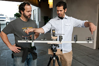
Rangefinder #2 is based off an interwar British model by Barr and Stroud. The main difference between this model and the first one is that it does not use mirrors only prism wedges and penta prisms to manipulate the lines of sight. I was lucky enough to find and download a training manual for this particular device and reverse engineer it. Unfortunately, in the interim I seem to have lost the particular web address it came from. Searching for "Barr and Stroud rangefinder" images will find several diagrams outlining its function, but I will try to post a link to the original documents I used once I find them. Generally speaking you look into the center eyepiece via an integrator prism (which I got from a old 3 lcd projection television) you see out through 2 objective lenses and then 2 penta prisms at the ends of the rangefinder, which direct your vision forward. There are 2 prism wedges between the objective lenses and the integrator in the prism. The one on the right of the photo is for calibration and the one on the left is for range finding. Other than the above mentioned optical components the range finder consists of 8020 aluminum stock, machined delrin and laser cut acrylic.
 |
| photo by Gayle Laird, Exploratorium |
Here you can see the range rule on the top of the sliding prism. When used the two channels of the Rangefinder appear red (the adjustable side) and blue (the fixed side) which makes its somewhat easier to orient yourself when looking through the Rangefinder. This is because the integrator prism had filters for red, green and blue for the corresponding lcds. I only used the 2 side channels, the green channel faces forward and is covered by cardboard. In general this set up was way more accurate than the first version. It was able to get the same reading over and over on objects under 1000 yards, but I found that it is very sensitive to vibration so it might not give the same readings after being moved. I continue to try and improve the design.
A detail of the eye piece and range rule
What you see looking through the eyepiece with coincidence not yet been achieved
A detail of the eye piece and range rule
What you see looking through the eyepiece with coincidence not yet been achieved


